Choosing TX and RX Filters
TX and RX filters select a specific portion of the RF or microwave signal based on the desired frequency and reject the rest of the signal being transmitted or received. The range of frequencies that are passed by a filter is called the pass-band, the ranges of frequencies that need to be rejected are called stop-bands. Unless otherwise specified, filters reflect energy in the stopbands, rather than absorb it.
A low-pass filter passes all signals below the cutoff frequency down to DC, and rejects higher frequencies. Use a LPF to eliminate harmonics, spurs, and intermodulation products that may occur above the fundamental frequency of a transmitter.
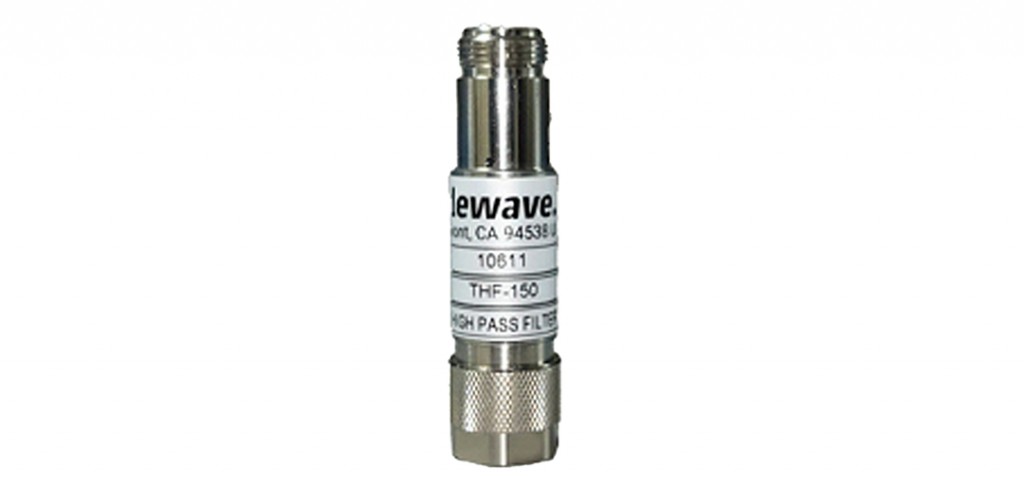
A high-pass filter allows all signals higher than the cutoff frequency to pass and rejects lower ones. This can be useful in eliminating spurs and noise that may occur below the fundamental frequency of a transmitter. They are also used to protect receivers from nearby high power transmitters.
A band-pass filter eliminates unwanted signals both above and below the desired frequency band, allowing only the intended frequencies to be received. For example, a bandpass filter can protect a receiver from nearby transmitters and adjacent channel interference.
In practice, all filters exhibit non-ideal behavior, such as insertion loss and ripple in the passband and non-infinite rejection in the stop-band(s). Rejection of low pass filters may degrade with increasing frequency. There may be re-entrant modes that cause additional passbands in band-pass filters at multiples of the desired frequency band. It is important for both suppliers and customers to understand all filter requirements.
The quality factor (Q) of a filter is an important figure of merit. Q is simply the ratio of stored energy to dissipated energy. The higher the Q, the lower the insertion loss. High-Q also helps when designing wideband bandpass filters.
Filters can be made from a variety of materials using many techniques. A few of the most commonly used filters today include:
Mechanical filters
This type of filter uses mechanical resonators that are coupled to the electrical circuit by piezo-electric transducers for receivers. It was widely used in the 1960s and early 1970s typically for low frequencies up to about 500 kHz. Though offering high levels of performance, mechanical filters can be very large and tend to drift over a wide range of temperatures.
Crystal filters
Crystal filters use piezoelectric quartz crystals as resonators in order to select a specific fixed frequency. This type of filter may be created with discrete crystals or by integrating the filter onto a single quartz wafer (called a monolithic crystal filter). The cut of the quartz crystal determines the crystal’s vibrating frequencies certain temperature characteristics of the component. Quartz crystals can have mechanical resonances with a very high Q factor (as high as 100,000), creating bandpass filters with very precise frequency characteristics. It also provides very high temperature stability. Crystal filters can be expensive and require extremely exacting manufacturing processes, but are reliable and efficient. They are also larger than some other forms of filters. They can only handle low power and therefore are used only as RX filters.
Ceramic filters are based on the same piezo-electric principle as crystal filters, but replace the quartz crystal with a ceramic resonator. Though they don’t have the high performance of crystal filters, they can be significantly less expensive to manufacture. Ceramic filters can be very small, and can provide sufficient Q factor for a wide of applications. Bulk acoustic wave (BAW) and surface acoustic wave (SAW) filters are ceramic filters, and are cheap enough to be used in cell phones.
Cavity filters
Resonant cavities select passband characteristics based on wavelengths that will resonate. Cavity filters are large at UHF frequencies where wavelengths are an appreciable fraction of a meter in length.
Lumped-element filters
Using capacitors and inductors in ladder networks is a well-known technique for filters at UHF and into the microwave frequency bands. Element values can be calculated directly from requirements using well-known formulas; the art of lumped element filters is absorbing unwanted parasitic elements such as series inductance of a capacitor into a design and making it behave to required specifications.
When choosing a filter, considerations include:
Desired frequency of operation
Insertion loss/ripple
Required rejection and stop bands
Power handling (for TX filters)
Filter size
Connector style
Cost
Temperature stability

